|
Notes on Tapers |
|
 Early
in
my re-building experience it became clear that I'd have to learn a
little about tapers. I couldn't just glue ferrules on pieces
of bamboo and expect them to be anything I'd want to
cast. I soon discovered that bamboo rod tapers get
passed around and everyone knows a good one, but few know why it's
good. Of course people who are good at it can take one look
at a chart, or graph, or some other table and tell exactly what a
rod will do. I can sorta tell, but I'm often still not
sure exactly what I'm looking at. Early
in
my re-building experience it became clear that I'd have to learn a
little about tapers. I couldn't just glue ferrules on pieces
of bamboo and expect them to be anything I'd want to
cast. I soon discovered that bamboo rod tapers get
passed around and everyone knows a good one, but few know why it's
good. Of course people who are good at it can take one look
at a chart, or graph, or some other table and tell exactly what a
rod will do. I can sorta tell, but I'm often still not
sure exactly what I'm looking at.
There are a lot of ways of judging a rod's character from it's taper. Some people chart the taper on graph paper. Others use formula. Still others computer models, such as Hexrod. Some use "deflection." Orvis started doing this with their "flex index" but the idea isn't really new. To use any of these method you have to have some idea about what a fly rod's doing and how well it's doing it. Reading this page won't make you an expert but it will give you a starting place. You have to go out and cast rods, then compare the tapers. But there are some general rules. |
| So the taper is always larger at the butt and progressively smaller as you move to the tip. This is often referred to as the "slope." The steeper the slope, the faster the rod. |
| In general a slope of .034 to .038 inches in a foot is a fast action: .028" to .033" is a medium action; .023 to .028 is a slow action rod. |
| Of course rods are thicker as line weight goes up. If the tiptop for a 4 wt is .065" then you can expect similar taper for a 5 wt to go around .070" to .072". |
| A rods general taper will increase by about .006" (Plus/minus) for each increase in line wt. |
| Two piece rods have more "flex" then three or four piece rods. The ferrules are considerably stiffer then the surrounding bamboo. That area of flexibility has been removed from the taper. While a 2 piece rod loses about 2 to 2½ inches under the ferrule, a 3 piece rod loses at least twice that. |
| Generally, the more sections a rod has the faster is will cast. |
| Now that's some VERY general rules of thumb and not all tapers abide by them. But it is a place to start |
|
How to measure a rod In the old days rods were measured from the butt to the tip. In the seventies, Garrison and Carmichael wrote the book A Masters Guide to Building a Bamboo Flyrod. In that book Garrison used a mathematical model that required starting at the tip. Over the next twenty five years almost all rods came to be measured from the tip. Although one, three, and six inch increments are used, the interval most used is five inches because it's easy to use in calculations. Although some rods were built to 64ths of an inch, today's rod cross sections are measured in thousandths (.001) of an inch. To do this some kind of special measurement tool is needed. The two basic tools used for measuring rods are a micrometer or calipers. While venire calipers can be used (and can be accurate to .0001 in) most rods are measured with a dial caliper. It's the quickest way and accuracy usually suffers less then .001. One other thing to take into consideration is that you're not actually measuring the bamboo, You're measuring the bamboo and any finish on the outside of the bamboo. Usually, you'll want to subtract .002 to .004 inches from your reading for varnish. I find that my old friend, masking tape, comes in handy when measuring a bamboo rod section. I can put a small strip of tape at each station (say every five inches from the tip.) and butt the side of my calipers against this tape. I know that I'll get the same readings each time. And it's a lot quicker then first finding then measuring each station, one at a time. |
| Make a chart. It should look something the one at the
right. It contains space for all the basic data you'll need
to record about your rod. The Title and date are very
important. I've got tables of numbers that have no
associated rod information with them. It's very easy to
create the information in the table, then forget what it refers
to. Include as much information as
you can. For example: "Second
Tip section for 8 ft. 3p 5wt. Wright and McGill field and
stream. To create duplicate tip section for
Jimmy. Done July 15, 2001" Always
put down more information then you need because you'll always need
it somewhere down the road..
The fields in the chart are as follows, Station is the position along the length of the section in inches. A, B and C are the flat to flat measurements of each of the three sides. Avg. is the average of the three sides. (you'll find that almost every rod you measure will be off from .001 to as much as .015 between different sides.) Slope is the difference between the current and preceding station. An example: Station 5 slope = the number in the station 5 average box minus the number in the Tip Average box. |
|
| Work with a good light. It makes the measuring device easy to
read. Keep clear of everything else. It's easy
to turn around, looking for something and break a rod section on a
desk or a table leg. Record each reading as you make it. (I
usually take all three readings at once and then write them down.
i.e. .071,.074, .078) If you create the data table using a computer spreadsheet it's easy to calculate the information. In fact you don't even have to put in the decimal point. (a + b + c)/3000 will convert 71 + 74 + 78 into .074333 or .074. If you find a station that is under a guide wrap, or in the middle of a ferrule, you have two choices. You can interpolate, taking the size above and below and create an increment of the slope, add it to the smaller number. Or you can measure both sides add them together, and average them . Either one should get you within tolerance. Surprisingly it's usually the slope that's more important then the actual dimensions. Once you've got all the numbers you'll be able to see a few things right away. You'll notice the slope can go from .006 to .022 over two five inch stations. You'll also notice that several stations have the same slope or a slope very much alike (.002+/- difference). They could be considered straight. A sudden change of .005 to .015 in a slope signifies a 'hinge' They seem like they're actually increasing stress, but in some ways, they relive stress around critical points. Hinges give a rod it's personality. In looking for the slope of a rod, don't consider the full length of the action ("tip to grip") because tips and the area just in front of the cork grip are often special cases. Let's take a 7½ ft rod as an example. the rod is 90 inches long, but the bottom 11 inches are taken up by the reel seat and grip. The action is 79 inches long. (most rod actions don't extend under the grip. A few do.) To find the slope of this rod, divide the action length by two and round to the nearest 5 inches. 79 / 2 = 39.5 rounded to 40". Next, using 5" increments, add and subtract an equal number of inches from that station. Using 20" we get 40 - 20 = 20 and 40 + 20 = 60. The slope between station 20 and 60 give us the slope in 40". We want to figure the slope in feet, so slope / 40 gives us the slope per inch. Multiply that slope by 12 for feet. Notice we don't have to use 20 inches as our base line. We could use 25" which would give us a slope from station 15 to station 65. Thirty inches would give us a slope from station 10 to station 70. However, the first and last 10 inches of an action are usually designed differently then the rest of the rod and if we include them in our calculations they can throw us off. The slope is only part of the information we use to evaluate a
rod. Remember a rod doesn't have to have a
consistent slope. Some of the best rods have slopes
that change from the tip to the butt. For example some
rods have a hinge close to the butt. This gives them
a "kick" Others have stiff butts and tips but a more
"modest" mid section. ( Often called Parabolic or
Simi-parabloic, they require a modified casting stroke to
get the most out of them, but people who like them won't trade
them for anything.) It might not be a bad idea to check
the slope for the first, second and third 1/3 of the action
length. Graphs Of course one easy way to compare tapers is to graph them on graphing paper. Things like hinges are easy to see when you compare two rods or compare a rod to it's slope. ( Yes you can chart the slope of a rod to see where it might be above or below the slope.) Once again, the tip and butt sections of a rod taper may be special considerations and may not give an exact indication of what they rod will actually cast like, but they are apparent if you're graphing the taper. |
| The illustration above is a graph of three very similar rods. The rod marked series 4 is the fastest of the three rods, while Series 3 is the slowest. Beyond this we see several places where the graph seems to flatten out. Those are the hinges for these rods. Without casting rods with similar hinges, it would be hard to tell if we really wanted a rod with these characteristics. |
|
Slope In the example, measuring from station 15 to station 65, the rod has a constant slope of about .014 per 5 inches. If we were to look only at the actual slopes between each point, it wouldn't tell us much. For example, what does the slight drop around station 75 mean? That's where the average slope number comes in. Remember we're only using the main part of the taper for our average. Using the tip and butt can lead to entirely different (and some would say erroneous) information. |
 |
| It looks like we'll have a slightly fast tip, with a hinge
starting somewhere between stations, 20 and 25. that hinge
will continue until we get close to station 35. Another
hinge is between stations 45 and 65. There will be a slight hinge close to station 75 but it won't be as significant as the other two. There are many ways to measure slope. It can be the difference between each station or the percent change per station. I once plotted slope using 4 methods and found that the plots all fell almost exactly in line with each other, So use what the method you like best. I chart slopes using the "between station" numbers. Changing tapers using slope For more information on understanding how changes in slope
change a fly rods action check out the articles "A discussion of
rod Tapers," by Don Anderson; "Rod Design by Controlled
Modification," by John Bokstrom and "Taper Design, by Frank
Neunemann, all in The Best of the Planing Form |
| Stress Curves
Stress curves were popularized in rod building by Garrison and Carmichael in their book A Master's Guide to Building a Bamboo Fly Rid . Stress curves are used to show the amount of stress any given point on a rod can handle. The idea is this will show how the rod will react when loaded. Very simply, where it will bend the most and at what point it will break. The stress at each point has to be calculated before the stress at the next point can be attained. Because the work is usually done in inches, and the calculation is very complex, very few people used them until the advent of the P.C. The Personal computer allowed the calculations be performed quickly and accurately. The only thing that was lacking was someone to write the program. That person was Wayne Cattanach, who included a floppy disk the first edition of his Handcrafting Bamboo Fly Rods. While the original program was primitive by today's standards, it revolutionized rod building. In the 2nd edition of Handcrafting... Wayne explains, in detail, the math behind the program. |
Cattanach 7'6"
(1) DT#5 2 pc.  Example of a Stress Curve for a 7½ ft. rod. |
| The best short explanation for stress curves and graphs was done
by Darryl Hayashida. He's allowed me to reprint it here in
it's entirety. (I've tried to adapt his ASCII art to
graphics. I hope he'll accept my humble attempts.) "In it's most basic use a stress curve shows you how close split cane rod is to breaking with the weight and length of line you specified. Garrison believed 200,000 ounces per square inch was a good, safe upper level. In reality you can go up to 220,000 or 230,000 without any problems. Garrison himself went up to 220,000 on his lighter rods. Garrison believed that below the 140,000 point the bamboo stopped flexing.
-Darryl Hayashida |
| Deflection Graphs
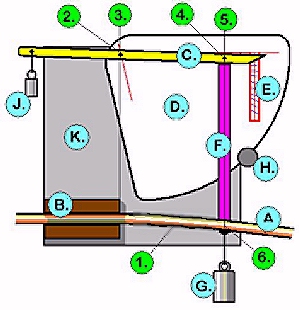
In his book The Technology of Fly Rods Don Phillips expounds on the old idea that you can tell a lot about how a fly rod will cast by placing weight at various places along the rod and measuring how far the rod bends. Don's original article appeared in 1973 in Flyfisherman, but even then It wasn't really new. Some rod companies would send out a large graph that could be placed on a wall and rigged to hold a rod by it's handle. A weight would be attached to the tiptop. The rod cold then be compared to lines on the graph, to tell the prospective buyer what they were getting. Today a few companies such as Orvis give information on the action of fly rods by reporting were they "flex." Don comes from an engineering background, so it's not surprising that his explanation is much more detailed and designed along engineering lines. The idea is fairly simple. If you immobilize a rod at some point, then place a known weight a known distance from the point the rod will bend -- in other words "flex." How far it will flex is measured as deflection. Most deflection measurements of the past were from the handle to the tip. Don points out that there are limitations to this approach. It will tell you how far a rod will flex, (and in Orivs' case, the point of greatest flex.) but it won't tell you much more. Don overcame this limitation by testing about 5 inches of the rod at a time. Do this to enough points you can come up with a deflection chart . The appeal of this method is it's portability. In theory, if two rods have the same deflection, then they should cast the same, no matter what they're made of. Like so much else in the rod building business this isn't completely true. The speed that a material will return from deflection and the material's weight are both variables that won't show up in a deflection curve. You'll need a jig to do the actual test. Here's a suggestion for building one.
There are three related variables, the length of the rod section being tested (in, in, in, etc.), the weight placed on the tested section (usually oz.) and the distance the tested rod section deflects, or bends (in inches). For example, a tip tested at five inches will flex under very little weight where a butt section tested at 9 inches will require much more weight to flex the same amount. It's easy to see that a way to give some commonality to the three is needed. Don came through for us again. It's an engineering formula. El = Pl3/3y
All these system are good ways to judge the taper of a fly rod. There are rod builders who swear by each one. Of course each has it's strong and weak points -- just as each has it's defenders and detractors. And I've only scratched the surface of each system. Once you find a system you like, you'll find all kinds of "tweaks" you can make so it will work it's best for you. But until you actually cast a few rods that you've graphed, or charted, you won't really know what you're looking at. So go find some of those rods of the old masters (or the new masters, for that matter) and see what they feel like. Then plot them out. Or better yet, go to the rod makers taper page and see if someone has already done a lot of the work for you! But remember, it starts with you casting a rod. Nothing else will do. |
Back to the Index

HomeStuff
Forms
Planes
Rrebuild
ToolsRod maker home